Posts

Showing posts from June, 2021

How To Make The Audio Cable | With 3.5mm TRS Audio Jack

Image
 The following diagrams explain the terminal lugs of the 3.5mm TRS audio jack and how it is soldering to the cable. This audio cable can be useful for making the next TinJunkBox audio amplifier project. TRS Stereo Jack  Cable Circuit Diagram   Note: TRS (T- Tip, R- Ring and S-Sleeve) The Item list. 3.5mm TRS Audio Jack -1 3mm Shielded 2-Core Audio Cable - 20-30Cm 3mm Heat Shrinking Tube -10cm Solder Wire -10cm Tools Soldering Iron -1 Micro Nipper or Side cutter -1 Knife -1 Crocodile nose plier -1 Tweezer -1 Appendix: Audio Cable  Headphone Circuit Diagram

How To Make The Audio Amplifier

Image
We know that the amplifier is the device that can increase the power of the signal.LM386 is audio power integrated circuit ( 1.25W )  most commonly used in TV, Radio, and Tape player audio amplifier stages. LM386 Circuit Diagram Item list for the amplifier. 1)10KΩ Volume Controller  - 1 2)10Ω Resisters  - 1 3)LM386 (IC)  - 1             ///(better to have extra ic) 4)8Ω,3W Speaker ( better 3 inch speaker)  - 1 5)10µF/16V Capacitor - 2 6)470µF/16V Capacitor - 1 7)0.047µF/50V or 100V Capacitor ( 0.047µF =47nF=47000pF/ 473)  - 1 8)Veroboard  - 1 9)9V Battery Holder Clip & 9V Battery  - 1 10)PCB Terminal Block - GMKDS 3/ 2 or similar type two pin terminal block   - 1 11)PCB Terminal Block - similar type three pin terminal block   - 1 12)Jumper Wire  - 2m 13)Short screen wire with stereo or mono audio Jack  - 1 14)Soldering Iron & Solder Wire (~1m)  - 1

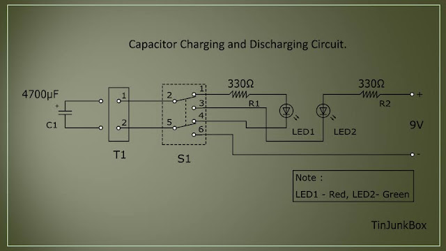
Capacitor Charging and Discharging Circuit.

Image
 This circuit is demonstrated the charge and discharge currents of the capacitor according to its capacitance. It also helps to identify the direction of the charge and discharge currents. Also, This circuit can be used to check capacitor conditions.  The Circuit Diagram Item list for the circuit: 330Ω Resistor ( Orange, Orange, Brown ) - 2 LED ( Red ) - 1 LED ( Green )  - 1 4700µF/16V ( or suitable voltage) Electrolytic Capacitor - 1 10µF/16V ( or suitable voltage) Electrolytic Capacitor - 1 Veroboard Piece - 1 9V Battery Holder Clip  - 1 9V Battery - 1 DPDT Slide Switch  - 1 Jumper Wire ( or one conductor copper wire) - 0.5m Soldering Iron & Solder Wire (0.3m)  -1 PCB Terminal Block - GMKDS 3/ 2 or similar type two pin terminal block -1 Appendix: DPDT Slide Switch •  Terminal Block - GMKDS 3/ 2  

IR Remote Control Tester Circuit

Image
Modern TV and DVD remote controls are using infrared signals to control their functions. When we press the button, the remote control front IR LED emits the intended pulse signal. When the photodiode is received an IR wave from a remote control, the remote control tester circuit is switched on its buzzer and LED according to the IR pulse signal. Item List for the IR Remoter Tester 10KΩ Resistor ( Brown, Black, Orange ) - 2 56KΩ Resistor ( Green, Blue, Orange ) - 1 100Ω Resistor ( Brown, Black, Brown - 1 0.22µF (224) Mylar Capacitor (Polyester Film Capacitor - 1 10µF/16V Electrolytic Capacitor  - 1 Photodiode (5mm IR Receiver ) - 1 BC547 Transistor - 1 3V Active Buzzer - 1 3 Pins mini SPDT slide switch /(ON/OFF)/suitable for Breadboard  - 1 Solderless Breadboard -1 Two numbers of 1.5V AA type Batteries with AA Type Battery Holder - 1 Jumper Wire - 0.5m Appendix: * Note: Change the components, If the circuit is operated in sunlight exploded places. SPDT Switch Mylar Capacitor BC547 Tra